Disassembling and Reassembling your Fruit Tester for field service
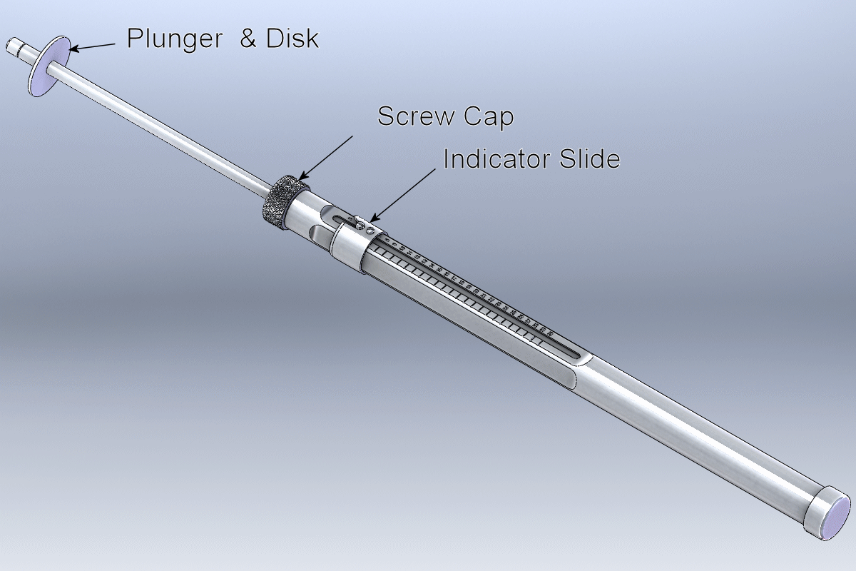
General View of your Fruit Tester with part identification
 Please note that the instructions and part numbers below are for the Model 30A OR 30B Tester.
  The process for the Model 10A is identical, but some of the part numbers are different.
 Consult the table at the bottom of this page to see the different Model 10A part numbers .
Your Fruit Tester has:
- A substantial Metal Body
- A metal rod (the Spring Rod) exiting the top end of the Body
- An Indicator Slide around the Body
- A knurled Screw Cap at the top of the Body
- A Plunger and Plunger Disk, normally mounted at the end of the Spring Rod
If the Plunger and Plunger Disk are not currently installed move ahead to Step-2
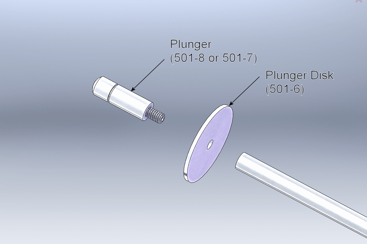
Step-1, Remove the Plunger and Plunger Disk
Remove the Plunger and Plunger Disk by unscrewing the Plunger from the spring rod. Turn the Plunger counter-clockwise while looking at the rounded end of the Plunger.
If necessary hold the Spring Rod and/or plunger with cushioned pliers. Cushioning the jaws of the pliers will prevent scarring of the metal parts.
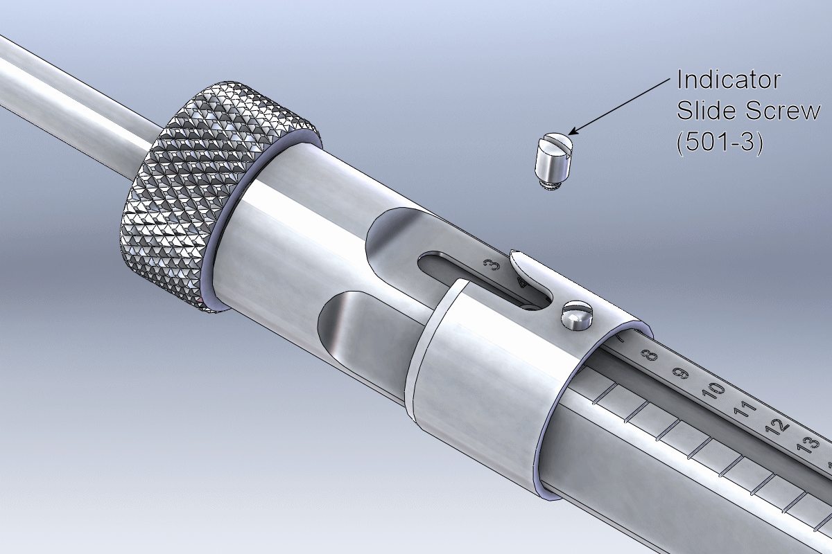
Step-2, Remove the Indicator Slide Screw
Using a small straight blade screwdriver, remove the Indicator Slide Screw by turning it counter-clockwise.
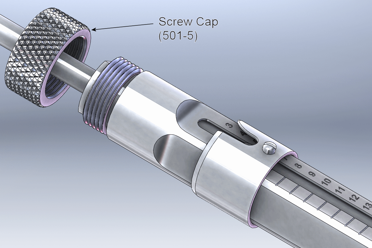
Step-3, Remove the Screw Cap
Remove the Screw Cap by turning it counter-clockwise while looking at the top of the Tester. Slide the Screw Cap off the end of the Spring Rod.
Step-4, Remove the Spring Rod and Inside Tube
The Spring Rod and the connected Inside Tube are removed by gently pulling on the Spring Rod.
In some cases the Boss, from which the Indicator Slide Screw was removed in step 3 (see picture) will catch on the end of the slot in the Body. If this happens,apply light pressure on the Boss with a finger tip or a pencil eraser to guide the Boss below the catching edge.
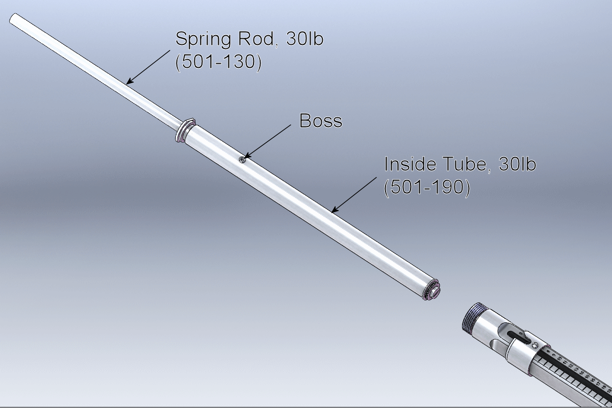
Step-5, Disassembly of the Inside Tube and Spring Rod
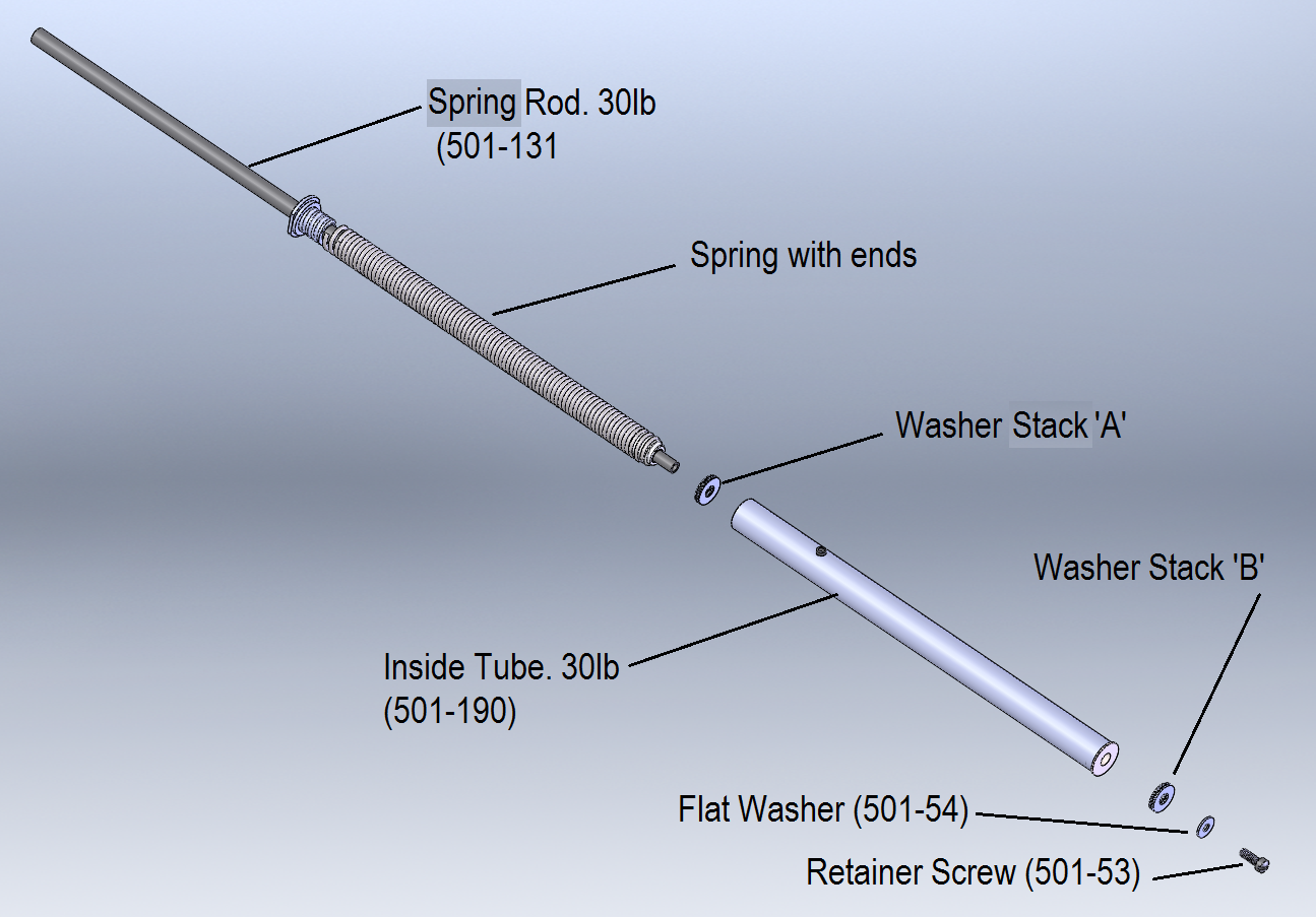
 Before continuing, count and record the number of Adjustment Washers in washer stack "B" located between the Shoulder Screw and the
bottom of the Inside Tube. Failure to do so may compromise reading accuracy after reassembly.
 DO NOT REMOVE the Spring from its end mounts or from the Spring Rod as this will undo the calibration of the Tester and will result in
inaccurate readings after reassembly.
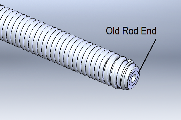
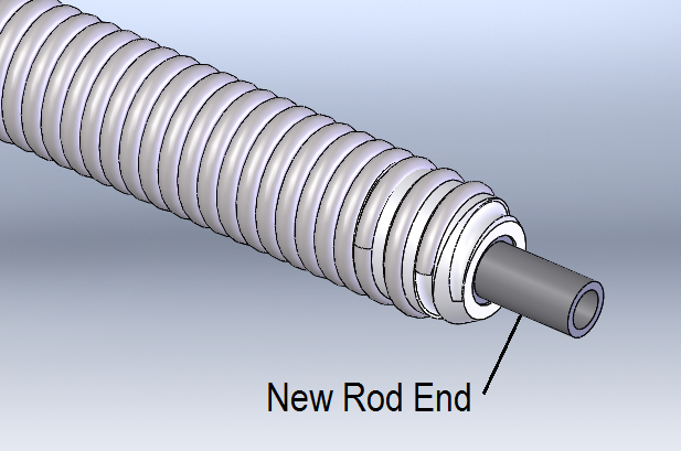
Please note that there are two different types of Spring Rods, the type of Spring Rod you have will determine how to go about Step-5
Look at the two images below and determine if you have a 'Old-Rod End' or a 'New-Rod End', then follow the appropriate section below.
|
|
|
|
|
Old Type Spring Rod Instructions
The remaining parts are held together by a Shoulder Screw, located at the bottom end of the Inside Tube. Using a medium (#2) straight blade screwdriver, remove the Shoulder Screw by turning it counter-clockwise.
At this point the Spring Rod can be removed from the Inside Tube. There are more Adjustment Washers in washer stack "A" within the Inside Tube, count and record the number of these parts as well.
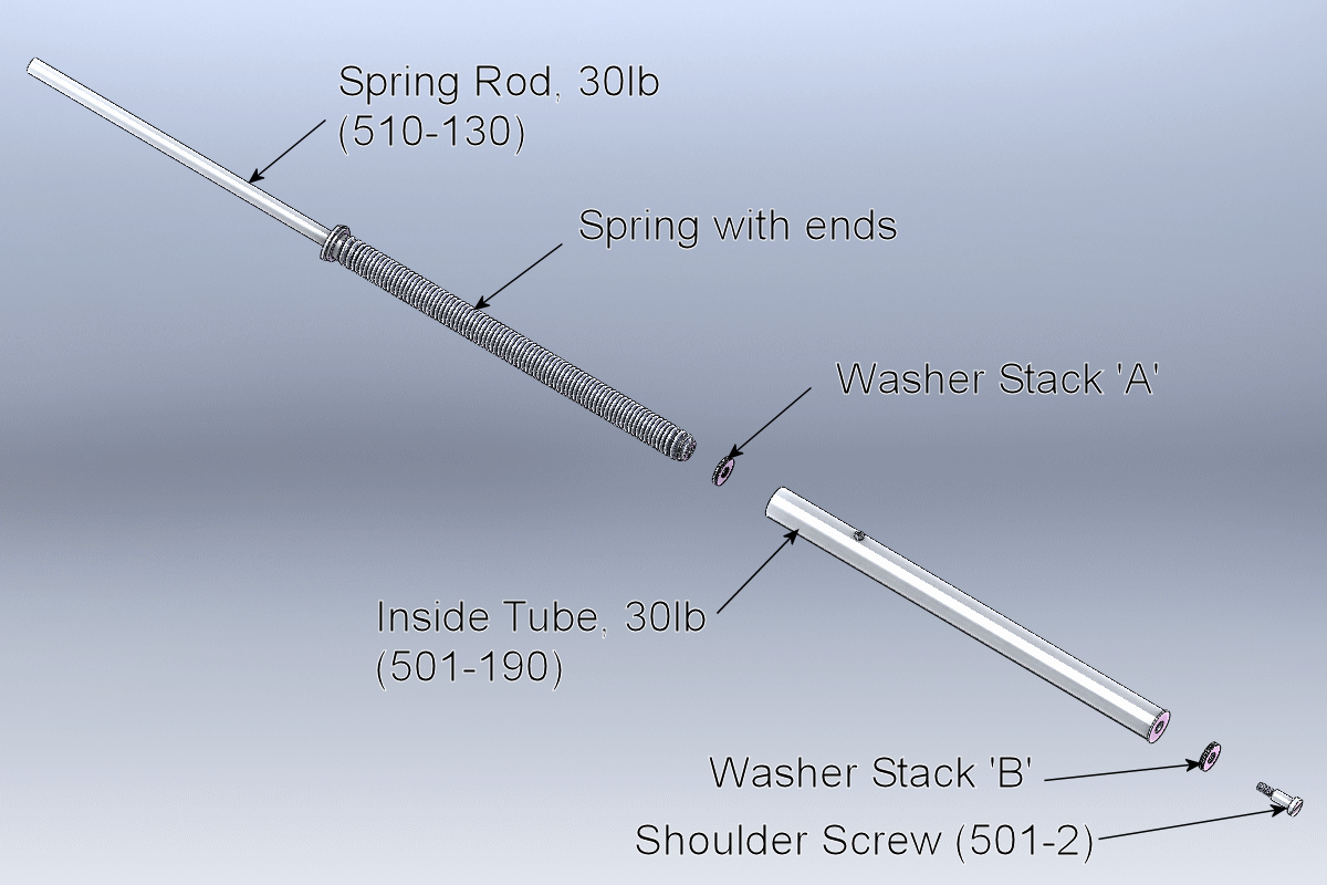
New Type Spring Rod Instructions
The remaining parts are held together by a Slotted head Screw and a flat washer, located at the bottom end of the Inside Tube. Using a medium (#2) straight blade screwdriver, remove the Screw and washerby turning it counter-clockwise.
At this point the Spring Rod can be removed from the Inside Tube. There are more Adjustment Washers in washer stack "A" within the Inside Tube, count and record the number of these parts as well.
Reassembly
Your Tester parts can now be cleaned and in some cases replaced as needed. To reassemble the Tester simply reverse the preceeding steps.
 Be sure to replace the right number of Adjustment washers in correct locations as per the counts recorded during disassembly.
 When replacing the Indicator Slide Screw, be sure not to cross-thread the boss. The screw should turn easily, if not back out the screw
and turn it about 1/2 turn then check for easy turning.
 On the old type Spring Rod it is difficult to get the washer stack "A" parts to seat properly by dropping them into the Inside Tube; Instead, hold the Spring Rod
with its bottom pointed up and balance the washer stack "A" parts on top of it, then lower the Inside Tube over the washers and Spring Rod. You
will need to push on the end of the Spring Rod (stretching the spring a bit) in order to be able to engage the Shoulder Screw.
The new type Spring Rods have a boss on the end so you an simply place the washer stack on the boss and easily reassemble the Tester.
-
Replacement Part numbers for models 10A, 30A, and 30B
Item Model 30B Model 10A Old Style Spring Rod 501-130 501-120 New Style Spring Rod 501-131 501-121 Inside Tube 501-190 501-180
